

Critical Gates Localization of Logic Circuits Based on Correlation Separation
-
摘要: 随着CMOS器件特征尺寸进入纳米量级,因高能粒子辐射等造成的电路失效问题日益严重,给电路可靠性带来严峻挑战。现阶段,准确评估集成电路可靠性,并以此为依据对电路进行容错加固,以提高电路系统可靠性变得刻不容缓。然而,由于逻辑电路中存在大量扇出重汇聚结构,由此引发的信号相关性导致可靠性评估与敏感单元定位面临困难。该文提出一种基于相关性分离的逻辑电路敏感门定位算法。先将电路划分为多个独立电路结构(ICS);以ICS为基本单元分析故障传播及信号相关性影响;再利用相关性分离后的电路模块和反向搜索算法精准定位逻辑电路敏感门单元;最后综合考虑面向输入向量空间的敏感门定位及针对性容错加固。实验结果表明,所提算法能准确、高效地定位逻辑电路敏感单元,适用于大规模及超大规模电路的可靠性评估与高效容错设计。Abstract: With the feature size of CMOS device entering the nanoscale, the circuit failure issue caused by high-energy particle radiation is becoming more and more serious, which brings severe challenges to the circuit reliability. At present, it is urgent to accurately evaluate the reliability of the integrated circuit and reinforce the fault tolerance of circuit, so as to improve the reliability of the circuit system. However, due to the large number of fan-out reconvergence structures in the logic circuit, the resulting signal correlation causes difficulties in reliability evaluation and critical gates location. This paper proposes critical gates location algorithm for logic circuit based on correlation separation. First, the circuit is divided into multiple Independent Circuit Structures (ICS); second, taking ICS as the basic unit to analyze fault propagation and signal correlation; Then, the circuit module after correlation separation and the reverse search algorithm is used to accurately locate the circuit critical gates; Finally, critical gates location and targeted fault tolerance reinforcement for the input vector space are comprehensively considered. The experimental results show that proposed algorithm can accurately and efficiently locate the critical gates of logic circuit, and it is suitable for reliability evaluation and efficient fault-tolerant design of large-scale and super-scale circuits.
-
Key words:
- Logic circuit /
- Failure /
- Correlation separation /
- Critical gate location /
- Fault tolerant design
-
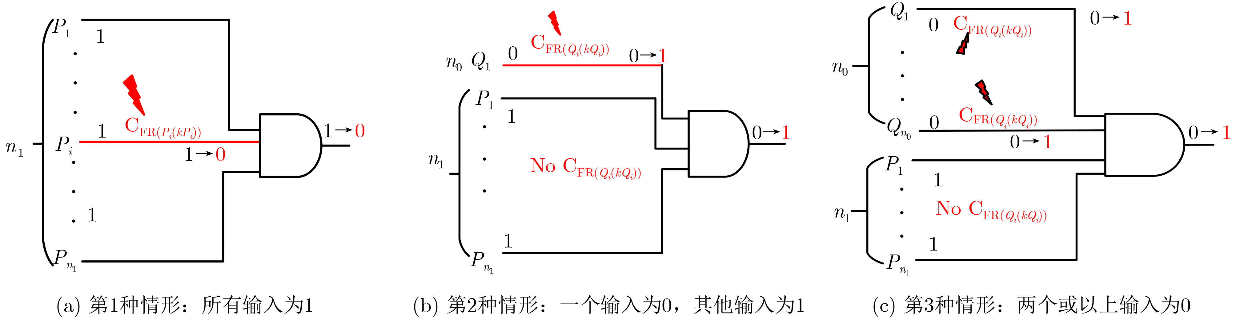
表 1 与门输出节点信息
输入向量 LVout PFIout Uout n1=n, n0=0 1 ${\rm{PFI}}_{P_1} $+···+${\rm{PFI}}_{P_{n-1}} $+FPG $ U_{P_1} $∪$U_{P_2} $∪···∪$ U_{Pn_1}$ n1=n–1, n0=1 0 ${\rm{PFI}}_{Q_1} $+FPG $ U_{Q_1} $ – $ U_{P_1 } $∪···∪$U_{Pn_1} $ n0≥2 0 FPG $ U_{Q_1 } $∩···∩$ U_{Qn_0 } $ – $ U_{P_1} $∪···∪$U_{Pn_1} $  下载: 导出CSV
算法1 VCGLA算法 输入:电路网表文件,输入向量 输出:向量敏感门 1. 通过COSEA算法计算电路所有节点的T
2. 计算CFR集合的输出:${U_{{\rm{CFR}}} } = \bigcup\limits_{i = 1}^{m_1} { {U_i} }$ //m1表示电路中CFR的
数量3. 计算CFI集合的输出: ${U_{ {\rm{CFI} } } } = \bigcup\limits_{i = 1}^{m_2} { {{\rm{C}}_{ {\rm{FIi} } } } }$//m2表示电路中CFI的
数量4. 创建VCG.set用于存储向量敏感门 5. FOR i =1 to n //n为UCFR中的CFR数量和UCFI中的CFI数量
之和6. Locate output gate of independent circuit structure 7. Node number are added to VCG.set 8. Calculate the number of critical inputs of the node: k 9. IF k == 0 10. GO to 5. 11. ELSE 12. FOR j = 1 to k 13. IF the critical gate j is the primary input or fanout
node14. GO to 12. 15. ELSE 16. GO to 7. 17. END IF 18. END FOR 19. END IF 20. END FOR 21. END
下载: 导出CSV
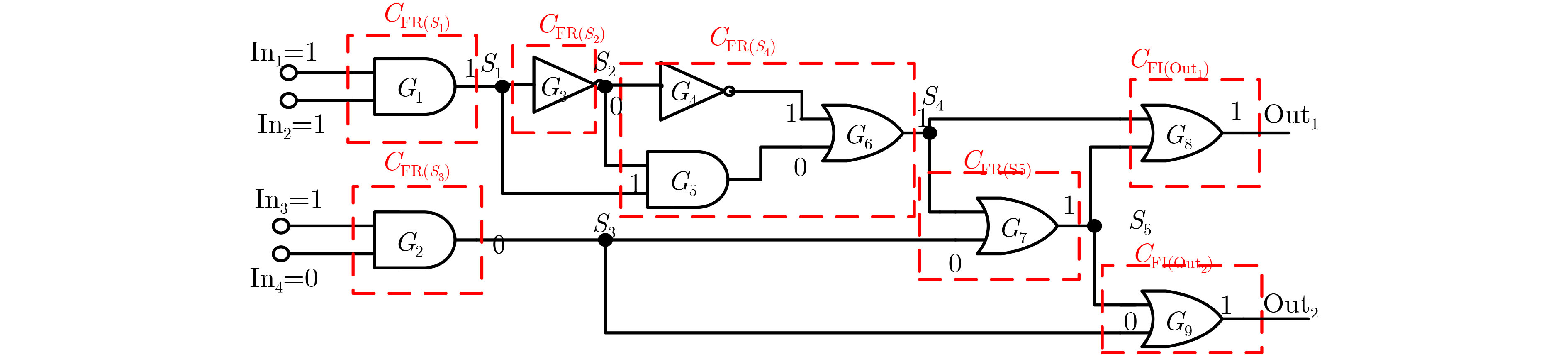
表 2 示例电路节点信息计算过程
节点 输入 LV CFI→CFR PFI U T G1 11 1 No PFIG1=FPG UG1={Ø} TG1={1, FPG, Ø} S1 1 1 ${\rm{PFR}}_{S_1} $=${\rm{PFI}}_{G_1} $=FPG ${\rm{PFI}}_{S_1} $=0 ${{U}}_{S_1} $= ${{U}}_{G_1} $∪${\rm{C}}_{{\rm{FR}}(S_1)} $={${\rm{C}}_{{\rm{FR}}(S_1)} $} ${{T}}_{S_1} $={1, 0, ${\rm{C}}_{{\rm{FR}}(S_1)} $} G2 10 0 No ${\rm{PFI}}_{G_2} $=FPG ${{U}}_{G_2 } $={Ø} ${{T}}_{G_2} $={0, FPG, Ø} G3 1 0 No ${\rm{PFI}}_{G_3} $=FPG ${{U}}_{G_3} $= ${{U}}_{S_1} $={${\rm{C}}_{{\rm{FR}}(S_1)}$} ${{T}}_{G_3} $={0, FPG, ${\rm{C}}_{{\rm{FR}}(S_1)} $} S2 0 0 ${\rm{PFR}}_{S_2} $=${\rm{PFI}}_{G_3} $=FPG ${\rm{PFI}}_{S_2} $=0 ${{U}}_{S_2} $= ${{U}}_{G_3} $∪${\rm{C}}_{{\rm{FR}}(S_2)} $={${\rm{C}}_{{\rm{FR}}(S_1)} $, ${\rm{C}}_{{\rm{FR}}(S_2)} $} ${{T}}_{S_2} $={0, 0, {${\rm{C}}_{{\rm{FR}}(S_1)} $, ${\rm{C}}_{{\rm{FR}}(S_2)} $}} G4 0 1 No ${\rm{PFI}}_{G_4} $=FPG ${{U}}_{G_4} $= ${{U}}_{S_2 } $={${\rm{C}}_{{\rm{FR}}(S_1)} $, ${\rm{C}}_{{\rm{FR}}(S_2)} $} ${{T}}_{G_4 } $={1, FPG,{${\rm{C}}_{{\rm{FR}}(S_1)} $, ${\rm{C}}_{{\rm{FR}}(S_2)} $}} G5 01 0 No ${\rm{PFI}}_{G_5 }$=2FPG ${{U}}_{G_5} $=${{U}}_{S_2} $–${{U}}_{S_1} $={CFR(S2)} ${{T}}_{G_5} $={0, 2FPG, ${\rm{C}}_{{\rm{FR}}(S_2)} $} G6 10 1 No ${\rm{PFI}}_{G_6} $=2FPG ${{U}}_{G_6} $=${{U}}_{G_4} $–${{U}}_{G_5} $={${\rm{C}}_{{\rm{FR}}(S_1)}$} ${{T}}_{G_6} $={1, 2FPG, ${\rm{C}}_{{\rm{FR}}(S_1)} $} S3 0 0 ${\rm{PFR}}_{S_3} $= ${\rm{PFI}}_{G_2 } $=FPG ${\rm{PFI}}_{S_3} $=0 ${{U}}_{S_3} $= ${{U}}_{G_2} $∪${\rm{C}}_{{\rm{FR}}(S_3)} $={${\rm{C}}_{{\rm{FR}}(S_3)} $} ${{T}}_{S_3 }$={0, 0, ${\rm{C}}_{{\rm{FR}}(S_3)}$} S4 1 1 ${\rm{PFR}}_{S_4 } $=${\rm{PFI}}_{G_6} $=2FPG ${\rm{PFI}}_{S_4} $=0 ${{U}}_{S_4} $= ${{U}}_{G_6 } $∪${\rm{C}}_{{\rm{FR}}(S_4)} $={${\rm{C}}_{{\rm{FR}}(S_1)} $, ${\rm{C}}_{{\rm{FR}}(S_4)} $} ${{T}}_{S_4} $={1, 0,{${\rm{C}}_{{\rm{FR}}(S_1)} $, ${\rm{C}}_{{\rm{FR}}(S_4)} $}} G7 10 1 No ${\rm{PFI}}_{G_7 } $=3FPG ${{U}}_{G_7} $= ${{U}}_{S_4} $ – ${{U}}_{S_3} $={${\rm{C}}_{{\rm{FR}}(S_1)} $, ${\rm{C}}_{{\rm{FR}}(S_4)} $} ${{T}}_{G_7} $={1, 3FPG, {${\rm{C}}_{{\rm{FR}}(S_1)} $, ${\rm{C}}_{{\rm{FR}}(S_4)} $}} S5 1 1 ${\rm{PFR}}_{S_5} $= PFIG7=3FPG ${\rm{PFI}}_{S_5} $=0 $U_{S_5} $= ${{U}}_{G_7} $∪${\rm{C}}_{{\rm{FR}}(S_5)} $={${\rm{C}}_{{\rm{FR}}(S_1)} $, ${\rm{C}}_{{\rm{FR}}(S_4)} $, CFR(S5)} ${{T}}_{S_5} $={1, 0,{${\rm{C}}_{{\rm{FR}}(S_1)} $, ${\rm{C}}_{{\rm{FR}}(S_4)} $, ${\rm{C}}_{{\rm{FR}}(S_5)} $}} G8 11 1 No ${\rm{PFI}}_{G_8} $= FPG ${{U}}_{G_8} $=${{U}}_{S_4} $∩${{U}}_{S_5} $={${\rm{C}}_{{\rm{FR}}(S_1)} $, ${\rm{C}}_{{\rm{FR}}(S_4) } $} $T_{G_8 } $={1, FPG,{${\rm{C}}_{{\rm{FR}}(S_1) } $, ${\rm{C}}_{{\rm{FR}}(S_4) } $}} G9 10 1 No ${\rm{PFI}}_{G_9}$=4FPG ${{U}}_{G_9 } $=${{U}}_{S_5} $-${{U}}_{S_3} $={${\rm{C}}_{{\rm{FR}}(S_1)} $,
${\rm{C}}_{{\rm{FR}}(S_4)} $, ${\rm{C}}_{{\rm{FR}}(S_5)} $}${{T}}_{G_9 } $={1, 4FPG, {${\rm{C}}_{{\rm{FR}}(S_1)} $, ${\rm{C}}_{{\rm{FR}}(S_4)} $. ${\rm{C}}_{{\rm{FR}}(S_5)} $}} Out1 1 1 No ${\rm{PFI}}_{{\rm{Out}}_1} $= ${\rm{PFI}}_{G_8} $=FPG ${{U}}_{{\rm{Out}}_1} $=${{U}}_{G_8 } $={${\rm{C}}_{{\rm{FR}}(S_1)} $, ${\rm{C}}_{{\rm{FR}}(S_4)} $} ${{T}}_{{\rm{Out}}_1} $ ={1, FPG,{${\rm{C}}_{{\rm{FR}}(S_1)} $, ${\rm{C}}_{{\rm{FR}}(S_4)} $}} Out2 1 1 No ${\rm{PFI}}_{{\rm{Out}}_2} $=${\rm{PFI}}_{G_9} $=4FPG ${{U}}_{{\rm{Out}}_2} $=${{U}}_{G_9} $={${\rm{C}}_{{\rm{FR}}(S_1)}$, ${\rm{C}}_{{\rm{FR}}(S_4)} $, ${\rm{C}}_{{\rm{FR}}(S_5)} $} ${{T}}_{{\rm{Out}}_2} $={1, 4FPG, {${\rm{C}}_{{\rm{FR}}(S_1)} $, ${\rm{C}}_{{\rm{FR}}(S_4)} $, ${\rm{C}}_{{\rm{FR}}(S_5)} $}}
下载: 导出CSV
算法2 CCGLA算法 输入:电路网表文件,电路敏感门阈值Th 输出:所有敏感门集合 1. FOR i = 1 to N//每个电路的输入向量数N 2. Randomly generate an input vector V(i) 3. VCG.set(i) = CALL Location algorithm of critical gate 4. END FOR 5. FOR i = 1 to Num//电路总门数Num 6. Count the number of times Gi in VCG.set //Gi 为第i个门 7. Calculate the sensitivity of Gi : $ {\text{G}}{{\text{S}}_{{G_i}}} = \dfrac{{{k_i}}}{N} $//ki是VCG.set
的Gi编号8. IF GSGi > Th 9. Add Gi to CCG.set //所有敏感门集合 10. END IF 11. END FOR 12. END
下载: 导出CSV
表 3 VCGLA与CGC-V1, V3, V4和V6方法的比较
电路 CGC-V1 VCGLA CGC-V3 CGC-V4 CGC-V6 avg.CG 时间(s) avg.CG max.err 时间(s) avg.CG max.err avg.err 时间(s) avg.CG max.err avg.err 时间(s) avg.CG max.err avg.err 时间(s) C432 53.7 118.2 53.7 0 0.10 52.3 18 2.1 0.04 52.0 18.0 1.7 20.30 50.7 26.0 3.0 10.30 C499 302.8 428.5 302.8 0 0.31 308.3 138 49.3 0.15 280.9 138.0 21.9 111.00 280.9 138.0 21.9 32.40 C880 218.6 5.1 218.6 0 0.16 223.2 40 10.3 0.06 215.3 17.0 2.4 2.50 212.8 30.0 4.9 1.00 C1355 225.2 1597.5 225.2 0 0.24 228.0 82 29.4 0.10 211.9 82.0 13.3 383.10 211.9 82.0 13.3 84.80 Avg 200.1 537.3 200.1 0 0.20 203.0 69.5 22.8 0.09 190.0 63.8 9.8 129.20 189.1 69.0 10.8 32.10
下载: 导出CSV
表 4 VCGLA与CGC-V3方法定位大规模电路的敏感门
电路 门数 向量数 VCGLA CGC-V3 avg.CG 时间(s) avg.CG 时间(s) avg.err max.err C1908 880 10000 404.8 0.34 405.0 0.14 0.4 85 C2670 1193 10000 449.2 0.46 468.6 0.25 20.9 191 C3540 1669 10000 500.3 0.59 439.6 0.43 113.0 425 C5315 2307 10000 809.2 0.99 824.0 0.40 15.0 73 C7552 3512 5000 1414.3 1.37 1488.3 0.72 74.6 256 S9234 5597 5000 2492.2 2.56 2540.7 1.94 51.9 176 S15850 9772 5000 5893.6 6.23 5952.6 6.90 61.3 134 S38417 22179 1000 14215.8 12.98 14914.3 11.45 706.2 862 b21 20027 1000 2780.1 28.07 2781.1 20.43 7.1 71 b22 29162 1000 4138.4 39.30 4141.6 28.60 13.6 118
下载: 导出CSV
-
[1] OATES A S and CHEUNG K P. Reliability of nanoelectronic devices[M]. VAN DE VOORDE M, PUERS R, BALDI L, et al. Nanoelectronics: Materials, Devices, Applications. Hoboken: Wiley, 2017: 317–330. [2] RAMIN R, MICHAEL N, and HU X S. Low-cost sequential logic circuit design considering single event double-node upsets and single event transients[C]. 2021 IEEE 39th International Conference on Computer Design (ICCD), Storrs, USA, 2021: 178–185. [3] TANG Du, HE Chaohui, LI Yonghong, et al. Soft error reliability in advanced CMOS technologies-trends and challenges[J]. Science China Technological Sciences, 2014, 57(9): 1846–1857. doi: 10.1007/s11431-014-5565-6 [4] VASILYEV N O, ZAPLETINA M A, and IVANOVA G A. The analysis of logic resynthesis methods to increase the fault tolerance of combinational circuits for single failures[C]. 2021 IEEE Conference of Russian Young Researchers in Electrical and Electronic Engineering (ElConRus), St. Petersburg, Russia, 2021: 2050–2053. [5] SIKANDER K, ZHAN Suoyue, and CHEN Chunhong. An analytical model for circuit reliability estimation[C]. 2021 IEEE International Midwest Symposium on Circuits and Systems (MWSCAS), Lansing, USA, 2021: 84–87. [6] LIU Baojun and CAI Li. Monte Carlo reliability model for single-event transient on combinational circuits[J]. IEEE Transactions on Nuclear Science, 2017, 64(12): 2933–2937. doi: 10.1109/TNS.2017.2772267 [7] KRISHNASWAMY S, VIAMONTES G F, MARKOV I L, et al. Probabilistic transfer matrices in symbolic reliability analysis of logic circuits[J]. ACM Transactions on Design Automation of Electronic Systems, 2008, 13(1): 1–35. doi: 10.1145/1297666.1297674 [8] XIAO Jie, LOU Jungang, and JIANG Jianhui. A fast and effective sensitivity calculation method for circuit input vectors[J]. IEEE Transactions on Reliability, 2019, 68(3): 938–953. doi: 10.1109/TR.2019.2897455 [9] HAN Jie, CHEN Hao, BOYKIN E, et al. Reliability evaluation of logic circuits using probabilistic gate models[J]. Microelectronics Reliability, 2011, 51(2): 468–476. doi: 10.1016/j.microrel.2010.07.154 [10] SINGH N S S, HAMID N H, ASIRVADAM V S, et al. Evaluation of circuit reliability based on distribution of different signal input patterns[C]. IEEE International Colloquium on Signal Processing and its Applications, Malacca, Malaysia: 2012: 5–9. [11] CHEN Chunhong and XIAO Ran. A fast model for analysis and improvement of gate-level circuit reliability[J]. Integration, 2015, 50: 107–115. doi: 10.1016/j.vlsi.2015.02.005 [12] 陈雷, 张瑶伟, 王硕, 等. FPGA三模冗余工具的关键技术与发展[J]. 电子与信息学报, 2022, 44(6): 2230–2244. doi: 10.11999/JEIT210330CHEN Lei, ZHANG Yaowei, WANG Shuo, et al. Key technology and development of triple modular redundancy tool for FPGA[J]. Journal of Electronics &Information Technology, 2022, 44(6): 2230–2244. doi: 10.11999/JEIT210330 [13] IBRAHIM W, SHOUSHA M, and CHINNECK J W. Accurate and efficient estimation of logic circuits reliability bounds[J]. IEEE Transactions on Computers, 2015, 64(5): 1217–1229. doi: 10.1109/tc.2014.2315633 [14] XIAO Jie, SHI Zhanhui, ZHU Weidong, et al. Uniform non-Bernoulli sequences oriented locating method for reliability-critical gates[J]. Tsinghua Science and Technology, 2021, 26(1): 24–35. doi: 10.26599/TST.2019.9010045 [15] XIAO Jie, SHI Zhanhui, YANG Xuhua, et al. BM-RCGL: Benchmarking approach for localization of reliability-critical gates in combinational logic blocks[J]. IEEE Transactions on Computers, 2022, 71(5): 1063–1076. doi: 10.1109/TC.2021.3071253 [16] IBRAHIM W. Identifying the worst reliability input vectors and the associated critical logic gates[J]. IEEE Transactions on Computers, 2016, 65(6): 1748–1760. doi: 10.1109/TC.2015.2458868 [17] IBRAHIM W and AMER H. Critical nodes count algorithm for accurate input vectors reliability ranking[C]. Proceedings of the Summer Computer Simulation Conference, Montreal, Canada, 2016: 19. [18] IBRAHIM W and IBRAHIM H. Multithreaded and reconvergent aware algorithms for accurate digital circuits reliability estimation[J]. IEEE Transactions on Reliability, 2019, 68(2): 514–525. doi: 10.1109/TR.2018.2876475 [19] CAI Shuo, HE Binyong, WU Sicheng, et al. An accurate estimation algorithm for failure probability of logic circuits using correlation separation[J]. Journal of Electronic Testing, 2022, 38(2): 165–180. doi: 10.1007/s10836-022-05996-y [20] XIAO Jie, CHEN Wenbo, LOU Jungang, et al. Identifying reliability-critical primary inputs of combinational circuits based on the model of gate-sensitive attributes[J]. IEEE Transactions on Computer-Aided Design of Integrated Circuits and Systems, 2022, 41(11): 4708–4720. doi: 10.1109/TCAD.2022.3142194 -

 下载:
下载:


图(6) / 表(6)
计量
- 文章访问数: 859
- HTML全文浏览量: 416
- PDF下载量: 84
- 被引次数: 0
