

One-pass Architectural Synthesis for Continuous-Flow Microfluidic Biochips Based on Deep Reinforcement Learning
-
摘要: 连续微流控生物芯片因其微型化、高可靠性和低样品消耗等优势,广泛应用于生物医学领域。然而,随着芯片集成度提升,其设计复杂性显著增加,传统分步式设计方法将绑定、调度、布局和布线等任务分步处理,各环节间信息交互不足,导致方案质量低、设计周期长。为此,该文提出一种基于深度强化学习的连续微流控生物芯片一步式架构综合方法。首先,通过图卷积神经网络提取状态特征,有效捕捉节点及其关系的信息;其次,在近端策略优化算法中结合A*算法和列表调度算法,从而得到具体的架构设计方案;最后,设计了一种多目标奖励函数,将生化反应时间、流道总长度及阀门数量进行归一化加权组合,并通过近端策略优化算法的策略梯度更新机制实现复杂决策空间的高效探索。实验表明,在基准测试用例上,与现有方法相比,该文方法在生化反应时间上优化了2.1%,流道总长度减少21.3%,阀门数量减少65.0%,且在较大规模芯片上仍能生成可行解。Abstract:
Continuous-Flow Microfluidic Biochips (CFMBs) are widely applied in biomedical research because of miniaturization, high reliability, and low sample consumption. As integration density increases, design complexity significantly rises. Conventional stepwise design methods treat binding, scheduling, layout, and routing as separate stages, with limited information exchange across stages, which leads to reduced solution quality and extended design cycles. To address this limitation, a one-pass architectural synthesis method for CFMBs is proposed based on Deep Reinforcement Learning (DRL). Graph Convolutional Neural networks (GCNs) are used to extract state features, capturing structural characteristics of operations and their relationships. Proximal Policy Optimization (PPO), combined with the A* algorithm and list scheduling, ensures rational layout and routing while providing accurate information for operation scheduling. A multiobjective reward function is constructed by normalizing and weighting biochemical reaction time, total channel length, and valve count, enabling efficient exploration of the decision space through policy gradient updates. Experimental results show that the proposed method achieves a 2.1% reduction in biochemical reaction time, a 21.3% reduction in total channel length, and a 65.0% reduction in valve count on benchmark test cases, while maintaining feasibility for larger-scale chips. Objective CFMBs have gained sustained attention in biomedical applications because of miniaturization, high reliability, and low sample consumption. With increasing integration density, design complexity escalates substantially. Traditional stepwise design methods often yield suboptimal solutions, extended design cycles, and feasibility limitations for large-scale chips. To address these challenges, a one-pass architectural synthesis framework is proposed that integrates DRL to achieve coordinated optimization of binding, scheduling, layout, and routing. Methods All CFMB design tasks are integrated into a unified optimization framework formulated as a Markov decision process. The state space includes device binding information, device locations, operation priorities, and related parameters, whereas the action space adjusts device placement, operation-to-device binding, and operation priority. High-dimensional state features are extracted using GCNs. PPO is applied to iteratively update policies. The reward function accounts for biochemical reaction time, total flow-channel length, and the number of additional valves. These metrics are evaluated using the A* algorithm and list scheduling, normalized, and weighted to balance trade-offs among objectives. Results and Discussions Based on the current state and candidate actions, architectural solutions are generated iteratively through PPO-guided policy updates combined with the A* algorithm and list scheduling. The defined reward function enables the generation of CFMB architectures with improved overall quality. Experimental results show an average reduction of 2.1% in biochemical reaction time, an average reduction of 21.3% in total flow-channel length, and an average reduction of 65.0% in additional valve count compared with existing methods. These improvements reduce manufacturing cost and operational risk. Conclusions A one-pass architectural synthesis method for CFMBs based on DRL is proposed to address flow-layer design challenges. By applying GCN-based state feature extraction and PPO-based policy optimization, the multiobjective design problem is transformed into a sequential decision-making process that enables joint optimization of binding, scheduling, layout, and routing. Experimental results obtained from multiple benchmark test cases confirm improved performance in biochemical reaction completion time, total channel length, and valve count, while preserving scalability for larger chip designs. -
1 DRL模型的训练过程
输入:时序图和设备库 输出:高效的芯片流层架构解 1 初始化: (1)actor网络$ \pi_{\theta}(\boldsymbol{a}|\boldsymbol{s}) $和critic网络$ V_{\phi}(\boldsymbol{s}) $的参数$ \theta $和$ \phi $ (2)设置超参数,包括学习率$ \alpha $、折扣因子$ \gamma $、批量大小B和训练
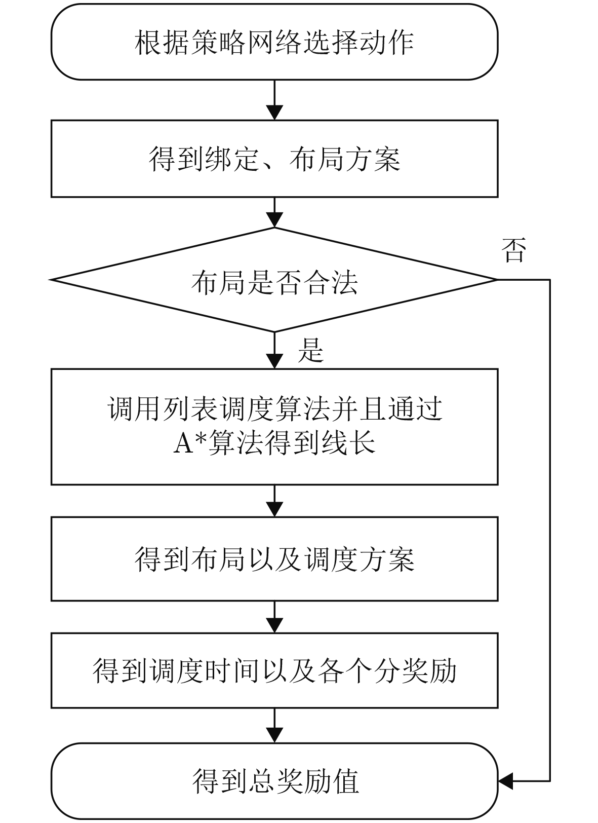
步数N(3)初始化经验回放缓冲区以及存储状态-动作-奖励序列 2 对于每个epoch: (1)While step$ \leq $100: (a)根据当前策略$ \pi_{\theta}(\boldsymbol{a}_t|\boldsymbol{s_{\mathit{t}}}) $选择动作 (b)通过执行动作$ \boldsymbol{a}_t $生成一个绑定和布局方案,并转移到环境
中的下一个状态$ \boldsymbol{s}_{t+1} $(c)如果布局合法,则结合列表调度算法和A*算法生成调度和
布线方案,得到总调度时间(d)计算总奖励值$ {r}_{t} $ (e)将$ (\boldsymbol{s}_t,\boldsymbol{a}_t,r_t,\boldsymbol{s}_{t+1}) $存入经验回放缓冲区 (f)$ \boldsymbol{s}_t\leftarrow\boldsymbol{s}_{t+1} $, step$ \leftarrow $step+1 (3)使用时间差分误差$ \delta_t=r_t+\gamma V_{\phi}(\boldsymbol{s}_{t+1})-V_{\phi}(\boldsymbol{s}_t) $计算优势函
数$ A_{\pi}(\boldsymbol{s}_t,\boldsymbol{a}_t) $(4)使用PPO策略梯度公式更新策略网络参数 3 经过多个epoch,最终得到一个高效的芯片流层架构解  下载: 导出CSV
表 1 实验中的测试用例
测试用例 |O| |E| |混合器| |加热器| |过滤器| |分离器| |检测器| |存储器| PCR 7 15 4 0 0 0 0 1 IVD 12 24 4 0 0 0 4 1 ProteinSplit 14 27 4 0 0 3 3 1 Synthetic1 10 15 2 2 2 0 2 1 Synthetic2 15 21 3 4 0 0 4 1 Synthetic3 20 28 4 4 0 4 0 1 Synthetic4 30 36 6 2 2 0 2 1 Synthetic5 50 60 8 2 2 0 2 1
下载: 导出CSV
表 2 本文方法执行3 ×10⁶回合训练所花费的时间(h)
测试用例 时长 测试用例 时长 PCR 2.5 Synthetic2 8.1 IVD 6.8 Synthetic3 10.5 ProteinSplit 6.5 Synthetic4 19.1 Synthetic1 6.2 Synthetic5 23.4
下载: 导出CSV
表 3 与BigIntegr[11]在生化反应时间、流通道总长度和额外引入的阀门数上进行对比
测试用例 尺寸 生化反应时间 流通道总长度 额外引入的阀门数 BI(s) DI(s) Imp (%) BI(mm) DI(mm) Imp (%) BI DI Imp (%) PCR 50×50 17 17 0.0 40 30 25.0 6 6 0.0 60×60 17 18 –5.9 50 30 40.0 5 2 60.0 70×70 17 18 –5.9 40 30 25.0 7 2 71.4 IVD 50×50 31 30 3.2 40 20 50.0 11 0 100.0 60×60 36 37 –2.8 80 60 25.0 10 0 100.0 70×70 37 37 0.0 90 60 44.4 9 0 100.0 ProteinSplit 50×50 89 89 0.0 40 30 25.0 7 4 42.9 60×60 88 89 –1.1 50 30 40.0 13 4 69.2 70×70 92 89 3.3 70 30 57.1 16 4 75.0 Synthetic1 50×50 33 33 0.0 30 30 0.0 8 4 50.0 60×60 33 33 0.0 50 30 40.0 10 2 80.0 70×70 33 33 0.0 50 60 –20.0 7 2 71.4 Synthetic2 50×50 44 45 –2.3 50 40 20.0 13 3 76.9 60×60 54 53 1.9 90 50 44.4 17 4 76.5 70×70 52 49 5.8 90 40 55.6 19 6 68.4 Synthetic3 50×50 69 67 2.9 40 50 –25.0 13 2 84.6 60×60 74 69 6.8 60 50 16.7 13 5 61.5 70×70 70 70 0.0 90 90 0.0 28 10 64.3 Synthetic4 50×50 65 58 10.8 30 40 –33.3 10 4 60.0 60×60 54 48 11.1 60 60 0.0 13 8 38.5 70×70 39 36 7.7 90 80 11.1 14 11 21.4 Synthetic5 50×50 113 102 9.7 70 50 28.6 7 3 57.1 60×60 - 89 - - 50 - - 4 - 70×70 - 89 - - 50 - - 4 - 平均值 - - - 2.1 - - 21.3 - - 65.0
下载: 导出CSV
表 4 不同算法在生化反应时间、流道总长度和额外引入的阀门数上的对比
测试用例 尺寸 生化反应时间 流通道总长度 额外引入的阀门数 A2C(s) PPO(s) Imp (%) A2C(mm) PPO(mm) Imp (%) A2C PPO Imp (%) PCR 50×50 25 17 32.0 40 30 25.0 7 6 14.3 60×60 26 18 30.8 50 30 40.0 4 2 50.0 70×70 26 18 30.8 60 30 50.0 6 2 66.7 IVD 50×50 60 30 50.0 40 20 50.0 2 0 100.0 60×60 77 37 51.9 60 60 0.0 2 0 100.0 70×70 68 37 45.6 60 60 0.0 2 0 100.0 ProteinSplit 50×50 122 89 27.0 40 30 25.0 7 4 42.9 60×60 122 89 27.0 40 30 25.0 7 4 42.9 70×70 161 89 44.7 40 30 25.0 6 4 33.3 Synthetic1 50×50 41 33 19.5 50 30 40.0 4 4 0.0 60×60 52 33 36.5 150 30 80.0 2 2 0.0 70×70 55 33 36.5 170 60 64.7 2 2 0.0 Synthetic2 50×50 91 45 50.5 70 40 42.9 10 3 70.0 60×60 110 53 51.8 140 50 64.3 6 4 33.3 70×70 91 49 46.2 70 40 42.9 10 6 70.0 Synthetic3 50×50 124 67 50.0 80 50 37.5 11 2 81.8 60×60 117 69 41.0 110 50 54.5 7 5 28.6 70×70 141 70 50.3 150 90 40.0 10 10 0.0 Synthetic4 50×50 91 58 36.3 60 40 33.3 6 4 33.3 60×60 98 48 51.0 80 60 25.0 10 8 20.0 70×70 57 36 36.8 110 80 27.3 13 11 15.4 Synthetic5 50×50 139 102 26.6 70 50 28.6 7 3 57.1 60×60 145 89 38.6 110 50 54.5 9 4 55.6 70×70 118 89 24.6 90 50 44.4 11 4 63.6 平均值 - - - 39.0 - - 38.3 - - 45.0
下载: 导出CSV
-
[1] CONVERY N and GADEGAARD N. 30 years of microfluidics[J]. Micro and Nano Engineering, 2019, 2: 76–91. doi: 10.1016/j.mne.2019.01.003. [2] CHOU H P, UNGER M A, SCHERER A, et al. Integrated elastomer fluidic lab-on-a-chip-surface patterning and DNA diagnostics[C]. The Solid State Actuator and Sensor Workshop, Hilton Head, South Carolina, 2000: 111–114. doi: 10.31438/trf.hh2000.27. [3] KINCSES A, VIGH J P, PETROVSZKI D, et al. The use of sensors in blood-brain barrier-on-a-chip devices: Current practice and future directions[J]. Biosensors, 2023, 13(3): 357. doi: 10.3390/bios13030357. [4] ARACI I E and QUAKE S R. Microfluidic very large scale integration (mVLSI) with integrated micromechanical valves[J]. Lab on a Chip, 2012, 12(16): 2803–2806. doi: 10.1039/c2lc40258k. [5] TSENG K H, YOU S C, LIOU J Y, et al. A top-down synthesis methodology for flow-based microfluidic biochips considering valve-switching minimization[C]. The 2013 ACM International Symposium on Physical Design, Nevada, USA, 2013: 123–129. doi: 10.1145/2451916.2451948. [6] 陈志盛, 朱予涵, 刘耿耿, 等. 考虑流端口数量约束下的连续微流控生物芯片流路径规划算法[J]. 电子与信息学报, 2023, 45(9): 3321–3330. doi: 10.11999/JEIT221168.CHEN Zhisheng, ZHU Yuhan, LIU Genggeng, et al. Flow-path planning algorithm for continuous-flow microfluidic biochips with strictly constrained flow ports[J]. Journal of Electronics & Information Technology, 2023, 45(9): 3321–3330. doi: 10.11999/JEIT221168. [7] HUANG Huichang, YANG Zhongliao, ZHONG Jiayuan, et al. Genetic-A* algorithm-based routing for continuous-flow microfluidic biochip in intelligent digital healthcare[C]. 18th International Conference on Green, Pervasive, and Cloud Computing, Harbin, China, 2023: 209–223. [8] KESZOCZE O, WILLE R, HO T Y, et al. Exact one-pass synthesis of digital microfluidic biochips[C]. The 51st ACM/EDAC/IEEE Design Automation Conference, San Francisco, USA, 2014: 1–6. doi: 10.1145/2593069.2593135. [9] WILLE R, KESZOCZE O, DRECHSLER R, et al. Scalable one-pass synthesis for digital microfluidic biochips[J]. IEEE Design & Test, 2015, 32(6): 41–50. doi: 10.1109/MDAT.2015.2455344. [10] MOHAMMADZADEH N, WILLE R, and KESZOCZE O. Efficient one-pass synthesis for digital microfluidic biochips[J]. ACM Transactions on Design Automation of Electronic Systems (TODAES), 2021, 26(4): 27. doi: 10.1145/3446880. [11] HUANG Xing, PAN Youlin, CHEN Zhen, et al. BigIntegr: One-pass architectural synthesis for continuous-flow microfluidic lab-on-a-chip systems[C]. 2021 IEEE/ACM International Conference on Computer Aided Design, Munich, Germany, 2021: 1–8. doi: 10.1109/ICCAD51958.2021.9643576. [12] HUANG Xing, PAN Youlin, CHEN Zhen, et al. Design automation for continuous-flow lab-on-a-chip systems: A one-pass paradigm[J]. IEEE Transactions on Computer-Aided Design of Integrated Circuits and Systems, 2023, 42(1): 327–331. doi: 10.1109/TCAD.2022.3166105. [13] MIRHOSEINI A, GOLDIE A, YAZGAN M, et al. A graph placement methodology for fast chip design[J]. Nature, 2021, 594(7862): 207–212. doi: 10.1038/s41586-021-03544-w. [14] 蔡华洋, 黄兴, 刘耿耿. 基于深度强化学习的连续微流控生物芯片控制逻辑布线[J]. 计算机研究与发展, 2025, 62(4): 950–962. doi: 10.7544/issn1000-1239.202440034.CAI Huayang, HUANG Xing, and LIU Genggeng. Control logic routing for continuous-flow microfluidic biochips based on deep reinforcement learning[J]. Journal of Computer Research and Development, 2025, 62(4): 950–962. doi: 10.7544/issn1000-1239.202440034. [15] KAWAKAMI T, SHIRO C, NISHIKAWA H, et al. A deep reinforcement learning approach to droplet routing for erroneous digital microfluidic biochips[J]. Sensors, 2023, 23(21): 8924. doi: 10.3390/s23218924. [16] LIM Y C, KOUZANI A Z, and DUAN W. Lab-on-a-chip: A component view[J]. Microsystem Technologies, 2010, 16(12): 1995–2015. doi: 10.1007/s00542-010-1141-6. -

 下载:
下载:


图(6) / 表(5)
计量
- 文章访问数: 601
- HTML全文浏览量: 382
- PDF下载量: 75
- 被引次数: 0
