

Design of 95~105 GHz SiGe BiCMOS Wideband Digitally Controlled Attenuator for Metasurface Antenna
-
摘要: 近年来,因对电磁波具备灵活的调控能力,超表面天线技术受到来自通信、雷达以及天线领域学者的广泛关注。其中,超表面天线单元中所使用的有源调控器件,是决定整个系统性能的最关键部件之一。该文基于0.13 μm SiGe BiCMOS工艺设计了一个95~105 GHz的五位宽带数控衰减器芯片。该衰减器采用了反射式和简化T型两种拓扑结构,其中4 dB与8 dB反射式衰减单元采用交叉耦合宽带耦合器代替传统的3 dB耦合器或定向耦合器,同时获得了高衰减精度和低插入损耗;而0.5 dB, 1 dB, 2 dB三个衰减单元均采用简化T型结构。此外,利用RC正斜率和负斜率校正网络分别应用于不同的衰减单元进行相位补偿,极大地改善了衰减器的附加相移。经过仿真验证,在95~105 GHz的感兴趣工作频率内,衰减器芯片在0.12 mm2的紧凑的尺寸下实现了0~15.5 dB的衰减范围,步进为0.5 dB,基态插入损耗小于2.5 dB,幅度均方根误差小于0.31 dB,附加相移均方根误差小于2.2º。所提出的W波段衰减器可作为一个关键部件赋能集成T/R的辐散一体化超表面天线系统的硬件实现。
-
关键词:
- SiGe BiCMOS /
- W波段 /
- 衰减器 /
- 交叉耦合宽带耦合器 /
- 超表面
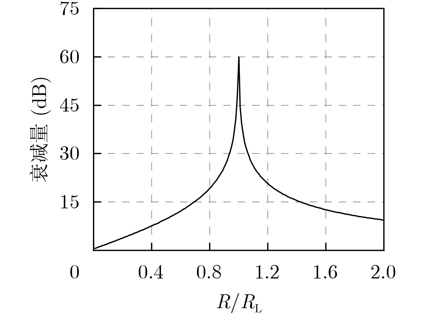
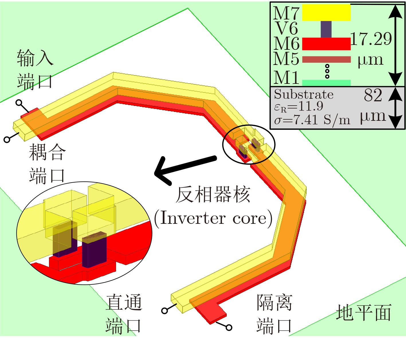
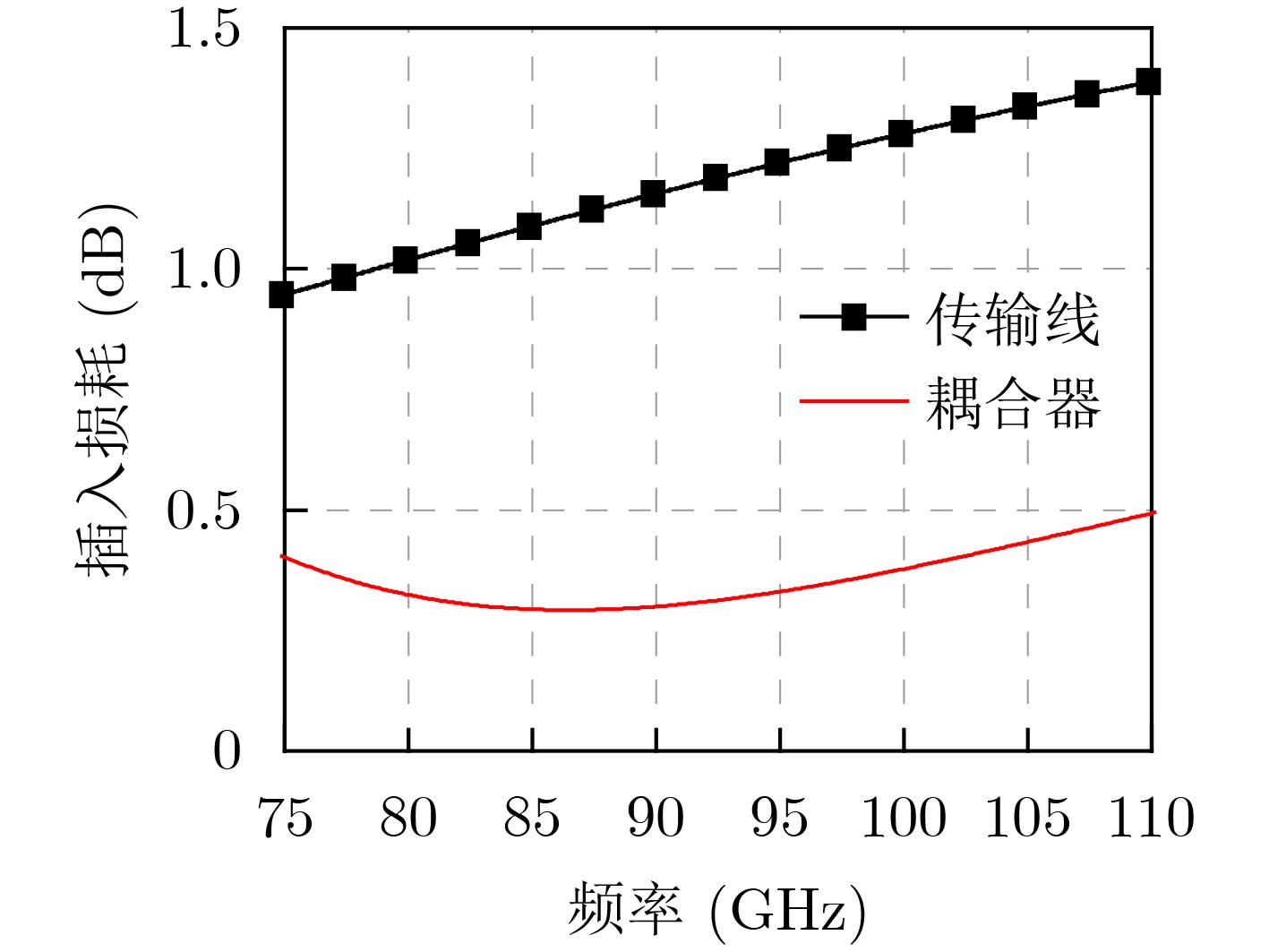
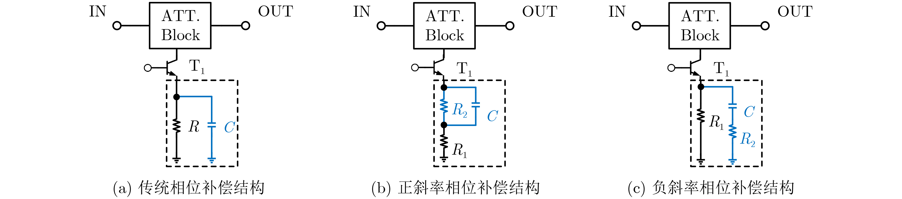
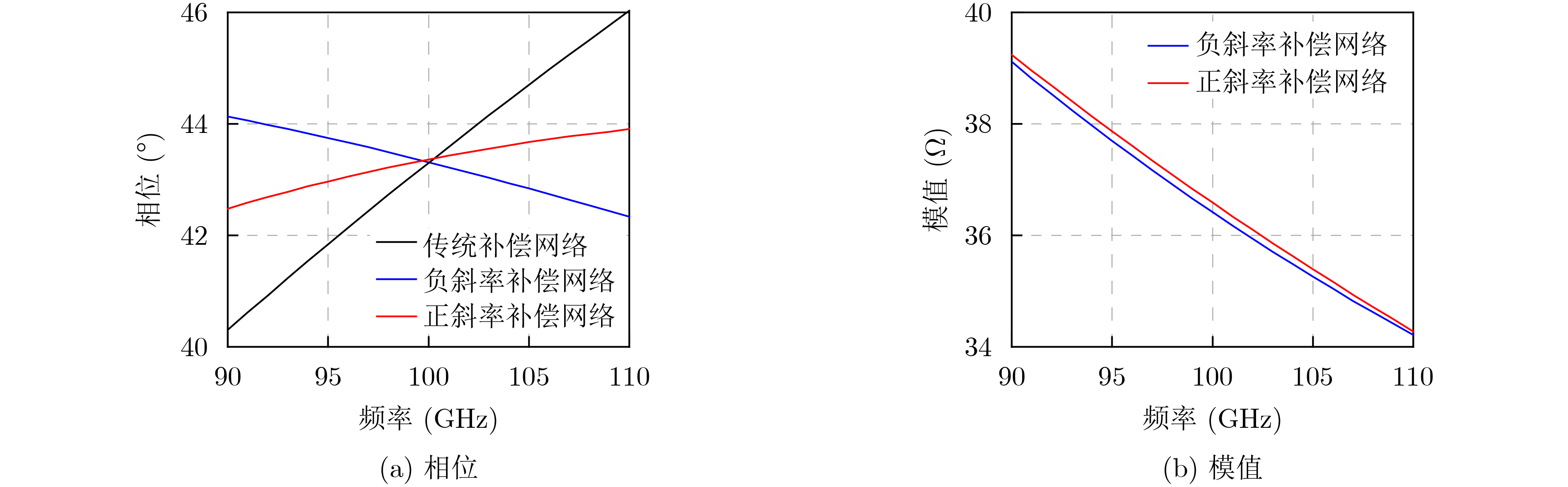
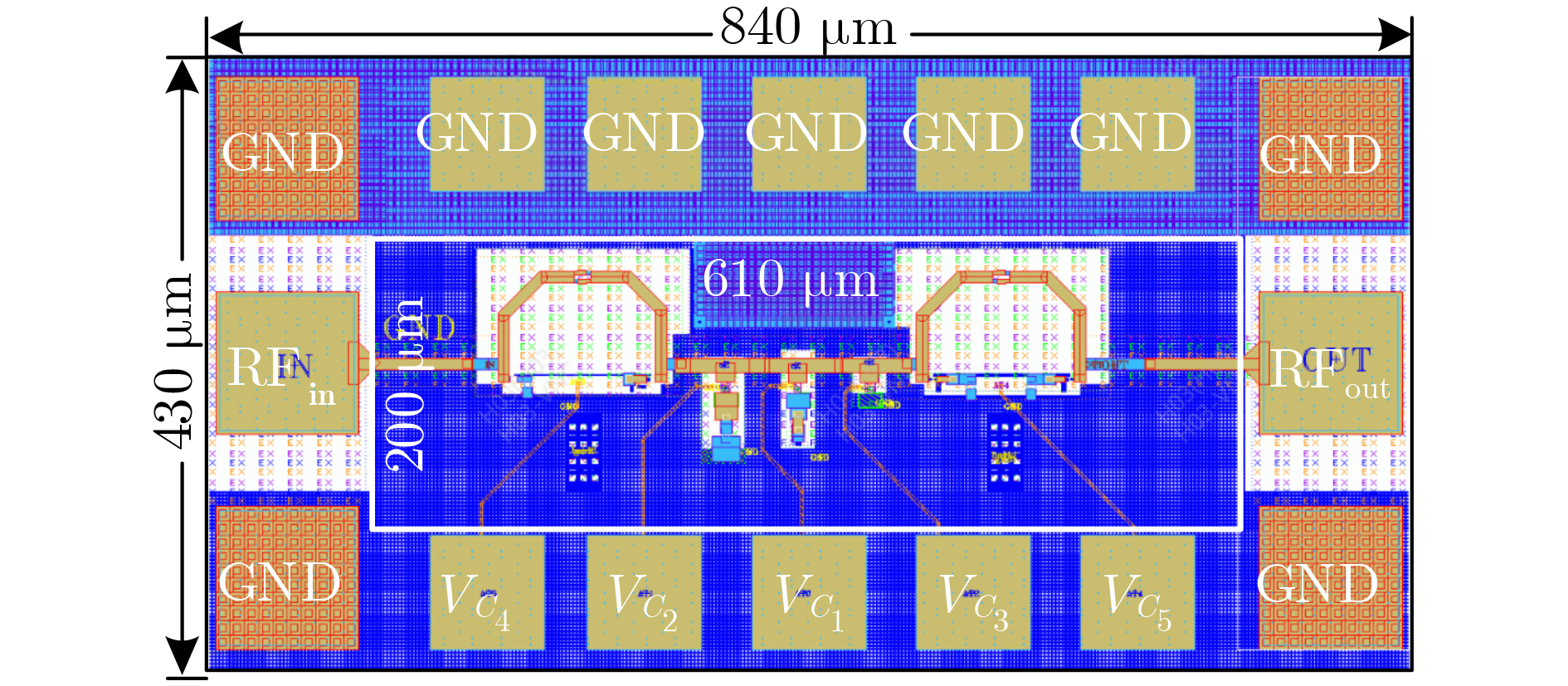
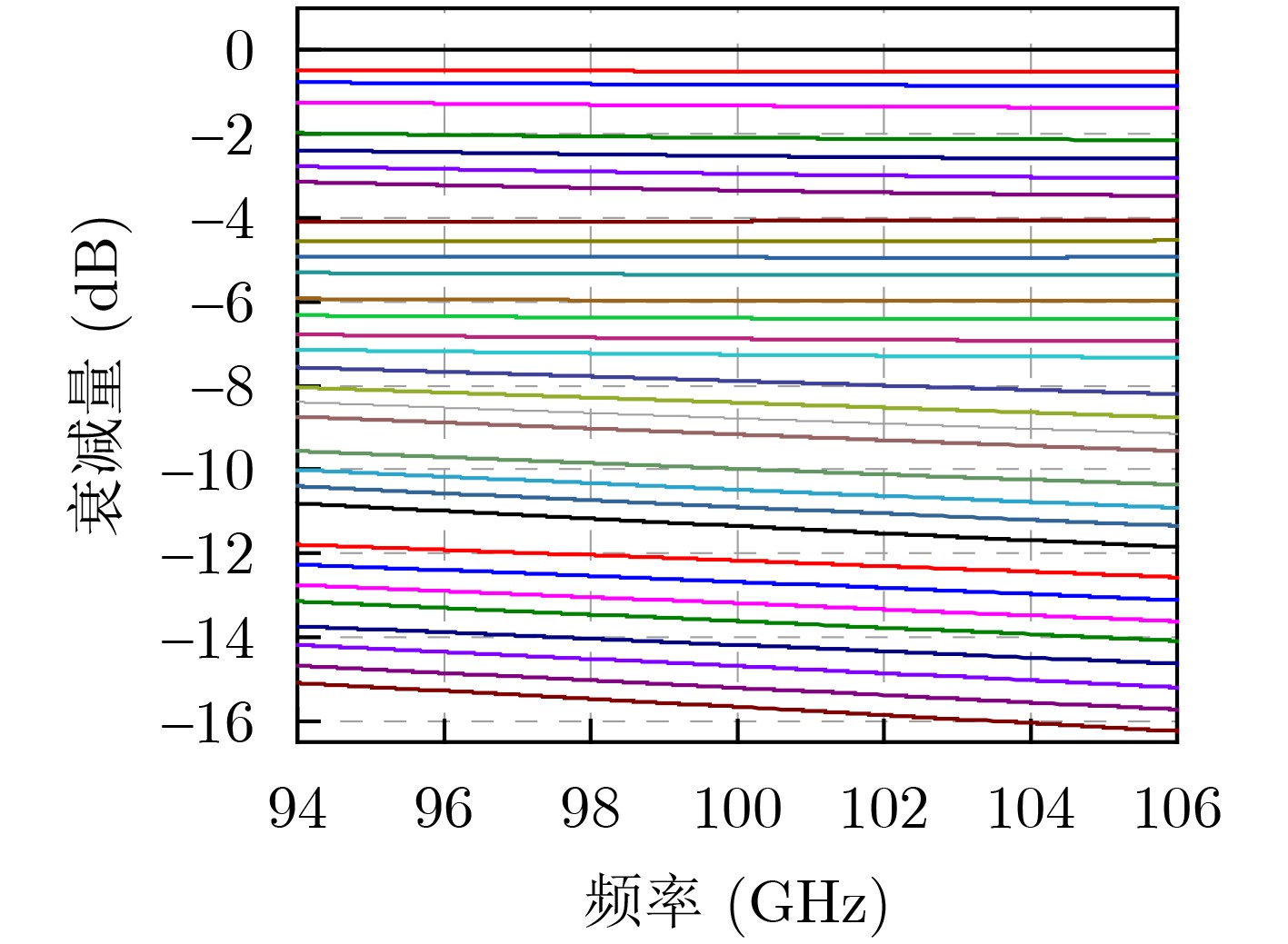
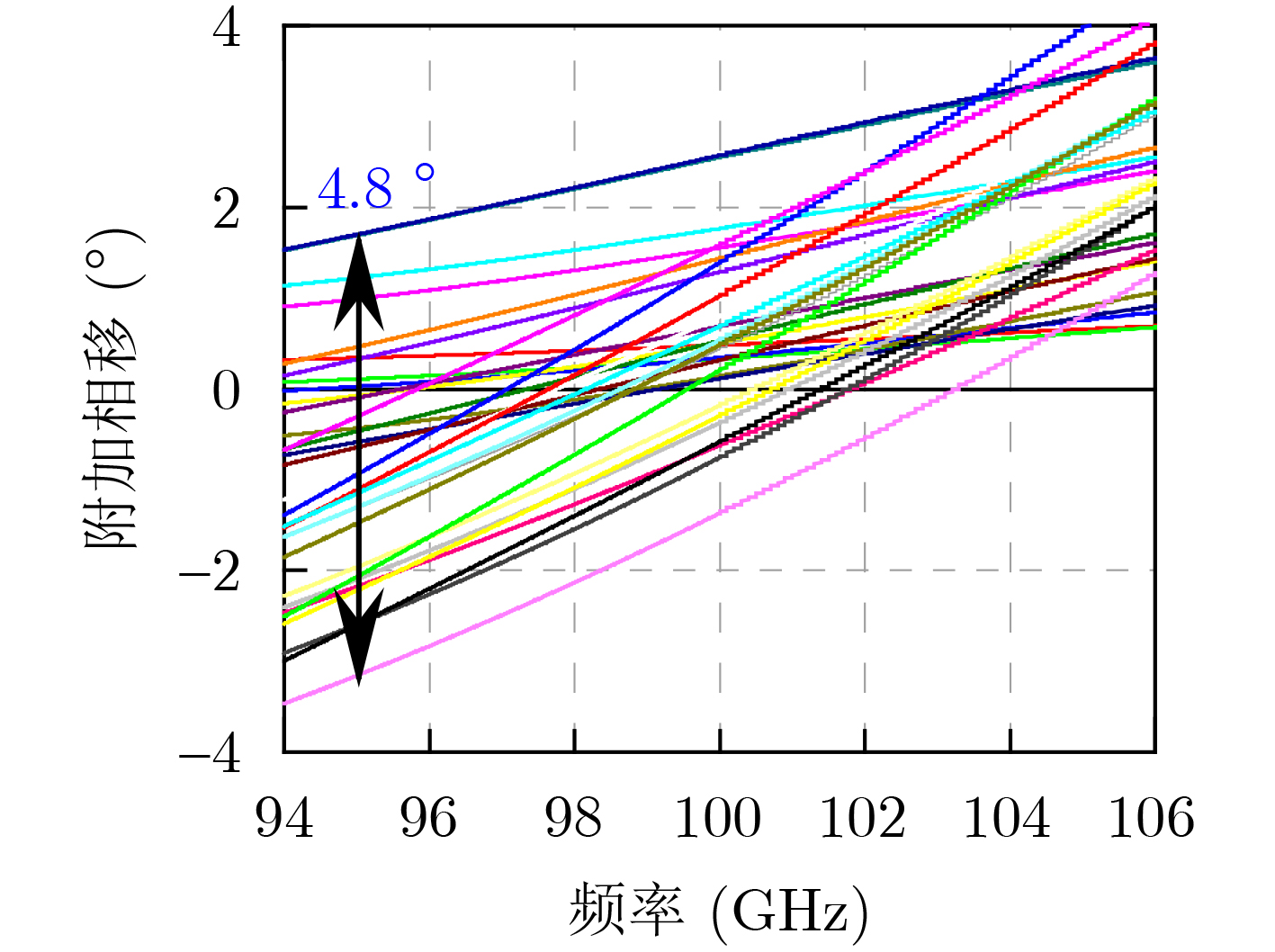
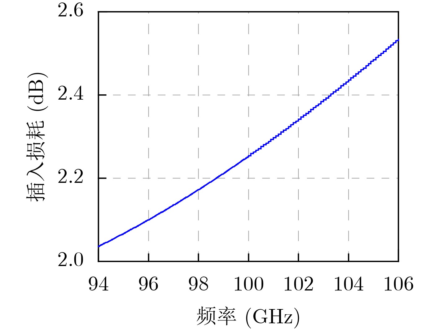
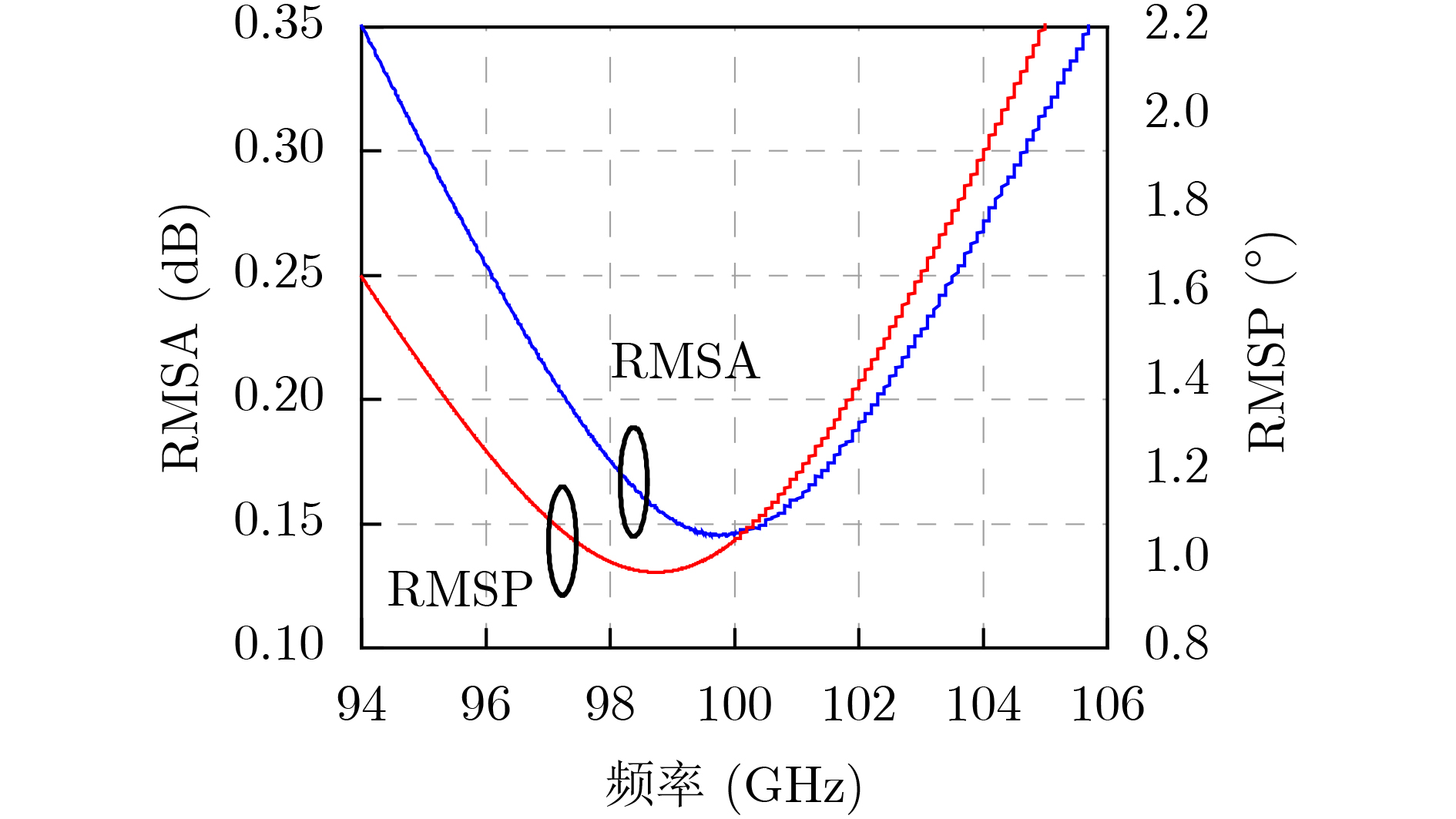
Abstract:Objective The W-band spectrum, spanning from 75 to 110 GHz, offers valuable spectrum resources, making it well-suited for high-speed wireless communication, radar detection, and biomedical imaging. Its lower atmospheric attenuation, compared to the commonly used 60 GHz band, further enhances its suitability for these applications. As modern wireless devices and electronic systems operate in increasingly complex electromagnetic environments, the demands on antenna systems are growing. These systems must independently control both radiated and scattered electromagnetic waves. Active phased array antennas, which integrate numerous transmit/receive (T/R) modules, provide precise control over the amplitude and phase of radiation elements, enabling superior manipulation of the radiated electromagnetic field. Meanwhile, rapidly advancing intelligent metasurface technology allows programmable, real-time modulation of scattered electromagnetic wave characteristics such as amplitude, phase, frequency, and polarization. This technology has attracted significant interest in the fields of communications, radar, and antenna systems. Consequently, metasurface antennas with active T/R modules offers a novel technological approach for efficient beam control of both radiated and scattered electromagnetic fields, providing new insights into solving complex electromagnetic environment problems. Digitally controlled attenuators (DSAs) are essential in metasurface antenna array systems, serving as millimeter-wave signal amplitude control modules. They primarily compensate for amplitude errors introduced by phase shifters or other components while also suppressing sidelobe levels in array antennas to enhance beam directivity. Additionally, these attenuators must exhibit minimal phase variation to reduce tracking errors, thus simplifying the calibration process. However, existing commercial millimeter-wave amplitude control chips are expensive and may face export restrictions, emphasizing the urgent need for high-performance, low-cost solutions to support the hardware implementation of metasurface antennas. Methods A 95 to 105 GHz DSA with 5-bit resolution is proposed. To address the issues of high insertion loss (IL), poor accuracy, and limited bandwidth in the large attenuation unit at W-band, a reflective structure based on a cross-coupled broadband coupler is proposed. The proposed coupler features a 180° inverter core and quasi-parallel stripline connections on both sides. At millimeter-wave frequencies (e.g., W-band), coupling capacitance introduced by the gaps creates a series resonance condition, achieving lower transmission loss and ensuring wide operational bandwidth. The 4 dB and 8 dB attenuation units, built using this structure, achieve high accuracy and low IL within a compact area. To minimize impedance mismatch during state switching, the attenuation units are cascaded in an order that reduces variations in amplitude and phase. Specifically, the 4 dB and 8 dB units are placed at the two ends of the attenuator to limit mutual interference. Smaller attenuation units (0.5 dB, 1 dB, and 2 dB) adopt a simplified T-type structure. The 0.5 dB unit, being more sensitive to impedance changes, is strategically positioned between the 1 dB and 2 dB units. Furthermore, phase changes during state switching are mitigated through a combination of positive- and negative-slope phase compensation networks. A positive-slope network is applied to the 4 dB unit, while negative-slope networks are used for the 0.5 dB, 1 dB, and 8 dB units. This dual compensation approach effectively avoids overcompensation, ensuring consistent amplitude and phase performance across all states, significantly improving the attenuator’s root means square (RMS) phase errors. Results and Discussions The layout of the proposed wideband DSA is shown in Fig. 10; the whole chip occupies a silicon area of 840 μm × 430 μm including all testing pads with a small core size of only 610 μm × 200 μm. It has five attenuation cells providing independent control of binary-coded attenuation levels of 0.5, 1, 2, 4, and 8 dB with a total of 32 states. Fig. 11 shows the simulated attenuation levels relative to the reference state for all 31 attenuation states within the desired frequency range of 95~105 GHz. The DSA achieves a dynamic attenuation range of 15.5 dB with a step resolution of 0.5 dB. The frequency response curves of adjacent states are evenly spaced with no overlap, indicating that the attenuator delivers precise amplitude control characteristics. The maximum phase variation relative to the reference state across all 31 attenuation states is less than 4.8°, as plotted in Fig. 12. As shown in Fig. 13, the IL in the reference state is less than 2.5 dB across the entire frequency band of interest. Fig. 14 illustrates the simulated RMS amplitude error and phase error versus frequency. The RMS amplitude errors remain below 0.31 dB over 95~105 GHz, while the RMS phase error is better than 2.2°. Table 3 summarizes the performance of the designed W-band attenuator and compares it with recently reported millimeter-wave DSAs. Compared to other attenuators, the proposed DSA demonstrates superior overall competitiveness, achieving low IL, high attenuation accuracy, and low RMS phase error within a compact chip size. While [6 ] achieves the lowest RMS phase error, it suffers from a high IL of 11.2 dB. In contrast, [20 ] offers excellent IL performance but is limited to a small attenuation range of only 4.7 dB.Conclusions In conclusion, the 5-bit W-band DSA presented in this paper, implemented in a 0.13 ${\text{µm}} $ SiGe BiCMOS process, offers an efficient and compact solution for wideband attenuation with low IL and minimal phase shift. The design integrates reflective and simplified T-type topologies, along with RC-based positive and negative slope correction networks applied to different attenuation units, enabling precise attenuation steps and optimized phase errors. The attenuator achieves an attenuation range of 0~15.5 dB with 0.5 dB steps over the 95~105 GHz frequency range, occupying a compact area of 0.12 mm2. Simulated results show an IL of less than 2.5 dB, RMS amplitude error below 0.25 dB, and RMS phase error under 2.2°. The proposed DSA can serve as a key component empowering the hardware implementation of an integrated T/R metasurface antenna system with simultaneous radiation and scattering control. -
Key words:
- SiGe BiCMOS /
- W-band /
- Attenuator /
- Wideband coupler with cross-coupling /
- Metasurface
-
表 1 等效电路模型元器件的参数值
器件 参数值 器件 参数值 L1 85.3 pH C1 0.5 fF L2 22.0 pH C2 2.7 fF L3 13.0 pH C3 12.8 fF R1 1.9 Ω C4 0.7 fF k 0.7  下载: 导出CSV
表 2 关键器件参数
器件 参数值 器件 参数值 器件 参数值 器件 参数值 T1,2(W/L) 120 nm/630 nm C1,2,4 20 fF R4 1298 ΩR9 81 Ω T3(W/L) 120 nm/ 1050 nmC3 12 fF R5 57 Ω R10 223 Ω T4(W/L) 120 nm/850 nm R1 126 Ω R6 2273 ΩT5(W/L) 120 nm/900 nm R2 301 Ω R7 190 Ω T6,7(W/L) 120 nm/ 1200 nmR3 1433 ΩR8 100 Ω W:发射极宽度;L:发射极长度
下载: 导出CSV
表 3 性能总结和已报道的硅基毫米波衰减器芯片对比
文献 2014[6] 2012[18] 2018[21] 2022[20] #本文 工艺 65 nm
CMOS180 nm
SiGe BiCMOS65 nm
CMOS130 nm
SiGe BiCMOS130 nm
SiGe BiCMOS频率(GHz) 50~110 57~64 80~110 190~220 95~105 拓扑结构 Distributed Distributed Coupled Coupled lines Reflected+T type 位数(bit)/步进(dB) 14/0.75 4/1.0 6/NA 4/0.35 5/0.50 衰减范围(dB) 0~10.0 0~11.8 0~14.5 0~4.7 0~15.5 插入损耗(dB) 11.2 11.0 4.5* 2.0 2.5 幅度均方根误差(RMSA)(dB) NA <1.54 <0.31 <0.34 <0.31 相位变化(º) <5.0 12.0* <12.0 NA <4.8 相位均方根误差(RMSP)(º) <1.4 <3.6 NA NA <2.2 面积(mm2) 0.38 0.94 0.06 0.03 0.12 *:估算;#:仿真结果
下载: 导出CSV
-
[1] CUI Tiejun, LIU Shuo, and ZHANG Lei. Information metamaterials and metasurfaces[J]. Journal of Materials Chemistry C, 2017, 5(15): 3644–3668. doi: 10.1039/C7TC00548B. [2] CHENG Qiang, ZHANG Lei, DAI Junyan, et al. Reconfigurable intelligent surfaces: Simplified-architecture transmitters—from theory to implementations[J]. Proceedings of the IEEE, 2022, 110(9): 1266–1289. doi: 10.1109/JPROC.2022.3170498. [3] ZHAO Chenxi, GUO Jiawei, LIU Huihua, et al. A 33–41-GHz SiGe-BiCMOS digital step attenuator with minimized unit impedance variation[J]. IEEE Transactions on Very Large Scale Integration (VLSI) Systems, 2021, 29(3): 568–579. doi: 10.1109/TVLSI.2020.3046016. [4] CHEON C D, RAO S G, LIM W, et al. Design methodology for a wideband, low insertion loss, digital step attenuator in SiGe BiCMOS technology[J]. IEEE Transactions on Circuits and Systems II: Express Briefs, 2022, 69(3): 744–748. doi: 10.1109/TCSII.2021.3111177. [5] RAO S G, CHEON C D, and CRESSLER J D. A millimeter-wave, transformer-based, SiGe distributed attenuator[J]. IEEE Microwave and Wireless Components Letters, 2022, 32(2): 145–148. doi: 10.1109/LMWC.2021.3118291. [6] KIM K, LEE H S, and MIN B W. V-W band CMOS distributed step attenuator with low phase imbalance[J]. IEEE Microwave and Wireless Components Letters, 2014, 24(8): 548–550. doi: 10.1109/LMWC.2014.2322442. [7] BAE J and NGUYEN C. A novel concurrent 22–29/57–64-GHz dual-band CMOS step attenuator with low phase variations[J]. IEEE Transactions on Microwave Theory and Techniques, 2016, 64(6): 1867–1875. doi: 10.1109/TMTT.2016.2546256. [8] HE Yang, ZHANG Tiedi, TANG Yichen, et al. Wideband pHEMT digital attenuator with positive voltage control driver[J]. IEEE Microwave and Wireless Technology Letters, 2023, 33(2): 295–298. doi: 10.1109/LMWC.2022.3215495. [9] JEONG J C, UHM M, JANG D P, et al. A Ka-band GaAs multi-function chip with wide-band 6-bit phase shifters and attenuators for satellite applications[C]. 2019 13th European Conference on Antennas and Propagation (EuCAP), Krakow, Poland, 2019: 1–4. [10] ZHANG Qingfeng, ZHAO Chenxi, ZHANG Shuangmin, et al. Mechanism analysis and design of a switched T-type attenuator with capacitive phase compensation technique[J]. IEEE Microwave and Wireless Technology Letters, 2023, 33(10): 1438–1441. doi: 10.1109/LMWT.2023.3303181. [11] LI Nayu, ZHANG Zijiang, LI Min, et al. A DC–28-GHz 7-bit high-accuracy digital-step attenuator in 55-nm CMOS[J]. IEEE Microwave and Wireless Components Letters, 2022, 32(2): 157–160. doi: 10.1109/LMWC.2021.3120934. [12] YUAN Ye, MU Shanxiang, and GUO Yongxin. 6-bit step attenuators for phased-array system with temperature compensation technique[J]. IEEE Microwave and Wireless Components Letters, 2018, 28(8): 690–692. doi: 10.1109/LMWC.2018.2849224. [13] BAE J, LEE J, and NGUYEN C. A 10–67-GHz CMOS dual-function switching attenuator with improved flatness and large attenuation range[J]. IEEE Transactions on Microwave Theory and Techniques, 2013, 61(12): 4118–4129. doi: 10.1109/TMTT.2013.2288694. [14] KU B H and HONG S. 6-bit CMOS digital attenuators with low phase variations for X-band phased-array systems[J]. IEEE Transactions on Microwave Theory and Techniques, 2010, 58(7): 1651–1663. doi: 10.1109/TMTT.2010.2049691. [15] BULJA S and RULIKOWSKI P. High dynamic range reflection-type attenuator[C]. 2018 IEEE Radio and Antenna Days of the Indian Ocean (RADIO), Wolmar, Mauritius, 2018: 1–2. doi: 10.23919/RADIO.2018.8572448. [16] YISHAY R B and ELAD D. W-band SiGe attenuators based on compact low-VSWR topologies[C]. 2017 IEEE MTT-S International Microwave Symposium (IMS), Honololu, USA, 2017: 638–641. doi: 10.1109/MWSYM.2017.8058650. [17] PU Yuqian, SHEN Hongchang, TANG Feihong, et al. Design of millimeter-wave reflective attenuators with capacitive compensation technique[J]. Journal of Southeast University (English Edition), 2023, 39(2): 153–160. doi: 10.3969/j.issn.1003-7985.2023.02.006. [18] BULJA S and GREBENNIKOV A. Variable reflection-type attenuators based on varactor diodes[J]. IEEE Transactions on Microwave Theory and Techniques, 2012, 60(12): 3719–3727. doi: 10.1109/TMTT.2012.2216895. [19] ZHU Wei, WANG Jiawen, WANG Ruitao, et al. 14.5 A 1V W-band bidirectional transceiver front-end with <1dB T/R switch loss, <1°/dB phase/gain resolution and 12.3% TX PAE at 15.1dBm output power in 65nm CMOS technology[C]. 2021 IEEE International Solid-State Circuits Conference (ISSCC), San Francisco, USA, 2021: 226–228. doi: 10.1109/ISSCC42613.2021.9365944. [20] ZHU Nengxu and MENG Fanyi. A 190-to-220GHz 4-bit passive attenuator with 1.4dB insertion loss and sub-0.4dB RMS amplitude error using magnetically switchable coupled-lines in 0.13-µm CMOS technology[C]. 2022 IEEE/MTT-S International Microwave Symposium - IMS 2022, Denver, USA, 2022: 746–749. doi: 10.1109/IMS37962.2022.9865616. [21] 赵丽. 新一代宽带无线互联网射频收发机及关键芯片的研究与设计[D]. [博士论文], 东南大学, 2018.ZHAO Li. Investigations on RF transceivers and related integrated circuits for a new generation broadband wireless internet[D]. [Ph. D. dissertation], Southeast University, 2018. (in Chinese). [22] LUO Jiang, HE Jin, CHEN Pengwei, et al. Micro-strip line 90° phase shifter with double ground slots for D-band applications[J]. Journal of Circuits, Systems and Computers, 2018, 27(12): 1850192. doi: 10.1142/S021812661850192X. -


 下载:
下载:


图(14) / 表(3)
计量
- 文章访问数: 1466
- HTML全文浏览量: 714
- PDF下载量: 55
- 被引次数: 0
